GPU Geometry Map Rendering – Part 1
I spent the past week moving my procedural planet renderer’s geometry map creation code from the CPU to the GPU. It didn’t go as smoothly as I would have liked, but in a way that was a good thing since I gained a much deeper understanding of some render pipeline things that I had been taking for granted. I also learned how to use PIX for shader debugging, which I now realize I should’ve done a long time ago. I hope to walk through some shader debugging in a later post.
CPU Geometry Maps
You may recall that a planet is defined as a cube with six faces. Each face can be thought of as a single flat plane when it comes to generating height values, and going forward we’ll do just that by considering only the front cube face.
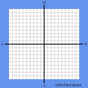
The cube face is defined with a coordinate system with (-1, -1) on the lower left, and (1, 1) at the upper right. This is very similar to clip-space, but we’ll refer to it as cube-face-space or just face-space.

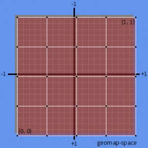
The geometry map can be thought of as a grid overlaying the cube face. Each position in the grid can also be thought of as a pixel in a heightmap. The grid can be as detailed as needed, but each dimension should match 2^n+1 – for example: 33×33, 65×65 – in order to help with subdividing. A very commonly used size is 33×33, and this is what I use. However, for this discussion we’ll use 5×5 to make things a bit easier to talk about. The geometry map has its own coordinate space, with (0, 0) on the lower left and (1, 1) on the upper right. Let’s call this geomap-space.
We need to generate a height value for each position in the geometry map grid. To do this we map from a geomap-space coordinate to a face-space coordinate, and use the result to generate the height at that position and store that height in the geometry map.
Here is a stripped down version of the CPU code I was using to create my geometry maps. The left, top, width, and height parameters define the face-space area we’re generating height values for. For a 5×5 geometry map over the entire face this function would be called like this:
CreateGeometryMap(-1, 1, 2, 2, 5, 5);
public void CreateGeometryMap(float left, float top, float width,
                              float height)
{
  // Calculate how far we need to move horizontally for each vertex
  // so the first is at "left", and the last is at "left + width".
  // Do the same for the vertical dimension. GeometryMapWidth and
  // GeometryMapHeight define the geometry map dimensions
  float horizontalStep = width / (GeometryMapWidth - 1);
  float verticalStep = height / (GeometryMapHeight - 1);

  float y = top - height; // start at the bottom

  for (int gy = 0; gy < GeometryMapHeight; gy++)
  {
    float x = left;

    for (int gx = 0; gx < GeometryMapWidth; gx++)
    {
      geometrymap[gx * GeometryMapWidth + gy] = GetHeightAt(x, y);
      x += horizontalStep;
    }

    y += verticalStep;
  }
}
Let’s walk through what it’s doing, in just the horizontal dimension since the vertical is exactly the same. This is a key to understanding how the GPU version works, so don’t skip over it.
The code iterates over the geometry map pixels from 0 to 4. The first pixel corresponds to -1 in face-space, the last pixel corresponds to +1 in face-space. The intervening pixels are found using the horizontalStep variable, which is calculated by dividing the face-space width by the geometry map width minus one. Remember that we passed in -1 for left, and 2 for width, so horizontalStep is 2 / (5 – 1), or 0.5.
The variable x starts out with the value left, or -1. Walking through the inner loop we get these values for x:
gx = 0, x = -1
gx = 1, x = -0.5
gx = 2, x = 0
gx = 3, x = 0.5
gx = 4, x = 1.0
If our geometry map width was 33, horizontalStep would be 2 / (33 – 1) or 0.0625. The first few steps of the loop would look like this:
gx = 0, x = -1
gx = 1, x = -0.9375
gx = 2, x = -0.875
gx = 3, x = -0.8125
gx = 4, x = -0.75
gx = 5, x = -0.6875
gx = 6, x = -0.625
And so on out to gx = 32 and x = 1. As mentioned before, determining y works exactly the same.
So, that pretty much takes care of the CPU method. It works great, it’s fairly simple, and it’s slower than a turtle crossing an Iowa road in winter. Well, to be fair, the GetHeightAt() function is slow because of the nature of the noise functions. Moving that functionality to the GPU is where we see the huge performance wins. So lets get to it.
GPU Geometry Maps
On the GPU side, we need to be able to generate exactly the same face-space coordinates as CalculateGeometryMap. Why does it have to be exact? Since the GPU only returns the height values, the CPU still has to determine the x and y values since they’re also used to create the actual vertices. If the x and y used by the GPU is different from the one used by CPU, bad things happen, like terrain patches shifting a pixel or two when they’re subdivided, and three 18 hour days spent trying to figure out why (yes, this is how I spent my week-long vacation from my “real” job).
When you think about needing the GPU to iterate over something in a general purpose way, what should immediately come to mind is texture coordinates. I’m enough of a n00b at this stuff that it didn’t immediately come to my mind, so while letting Google do my thinking for me I ran across the Britonia blog, which looks like it will prove to be a very helpful resource when it comes to this whole planet creation business.
The idea I came across on that blog is to have the GPU interpolate texture coordinates in such as way as they match the x and y values on the CPU version. It was a breakthrough moment for me, I ran with it, and soon came to a screeching halt. Let’s start with the “running with it” part though.
First thing is to set up a render target which will hold our geometry map. The render target needs to match the size of our desired geometry map, so we just create it with the same dimensions. (Note that all of this code will be available in the sample linked at the end of part 2 of the article).
const int Width = 5;
const int Height = 5;

renderTarget = new RenderTarget2D(
  GraphicsDevice, Width, Height, 1,
  SurfaceFormat.Color, MultiSampleType.None,
  0, RenderTargetUsage.DiscardContents);
Note that I’m using SurfaceFormat.Color here. In the actual version you want SurfaceFormat.Single so you get 32-bit floating point goodness. In this case Color works out fine since we’re going to be examining the output in PIX and don’t really care what the final format looks like.
Next thing is to set up a full screen quad with pre-transformed vertices. Pre-transformed means we’re defining the vertices in clip space, so no transformation is necessary in the vertex shader. We can just pass the coordinates directly to the vertex shader with no changes. Also, we define texture coordinates that cover the full quad, so the GPU will interpolate them from 0 to 1 for us as it processes each pixel.
vertices = new VertexPositionTexture[4];
vertices[0] = new VertexPositionTexture(
  new Vector3(-1, 1, 0f), new Vector2(0, 1));
vertices[1] = new VertexPositionTexture(
  new Vector3(1, 1, 0f), new Vector2(1, 1));
vertices[2] = new VertexPositionTexture(
  new Vector3(-1, -1, 0f), new Vector2(0, 0));
vertices[3] = new VertexPositionTexture(
  new Vector3(1, -1, 0f), new Vector2(1, 0));
Note that “full screen” really means “full render target”. Because the render target is 5×5, and we’re rendering a full screen quad to it, the quad will contain 5×5 pixels, and our pixel shader will be executed for each of those pixels, with the texture coordinates interpolated over the pixels from 0 to 1 in each dimension. (Yes, the screeching halt will soon be upon us).
The last thing we need is to tell the pixel shader what face-space dimensions to work with. These are the same parameters passed to the CreateGeometryMap function on the CPU.
quadEffect.Parameters["Left"].SetValue(-1.0f);
quadEffect.Parameters["Top"].SetValue(1.0f);
quadEffect.Parameters["Width"].SetValue(2.0f);
quadEffect.Parameters["Height"].SetValue(2.0f);
To rehash a bit, CreateGeometryMap required the face-space dimensions (left, top, width, height), as well as constant values defining the geometry map dimensions. For our pixel shader, the face-space dimensions are taken care of by the effect parameters, and the geometry map dimensions are taken care of by the render target dimensions.
All that’s left now is drawing the quad.
GraphicsDevice.DrawUserPrimitives(
  PrimitiveType.TriangleStrip, vertices, 0, 2);
And, now the screeching halt:
The results were close, but not what I expected. Neighboring geometry maps were off by a pixel or two, and when quad tree nodes split, all the geometry seemed to shift a pixel or two. It was all very distracting and ugly. After spending quite awhile walking through code and trying to figure out where I went wrong, I finally decided it was time to install PIX.
And the rest will have to wait until the next post, where I’ll go through the shader itself, and walk through debugging it in PIX to see what’s going on.

2 thoughts on “GPU Geometry Map Rendering – Part 1”
Comments are closed.